Building Sentinel: A Home Sentry Robot with Raspberry Pi and Home Assistant
A few months ago I had this itch I couldn’t quite scratch — I wanted a way to check in on my house remotely — specifically to keep an eye on my dogs while I was away. A static camera only covers one spot, and dogs don’t stay in one spot. I wanted something that could move. Something I could drive around from my phone and point the camera wherever I needed. I’d been messing around with Home Assistant for a while and thought: why not make this a full HA-integrated device?
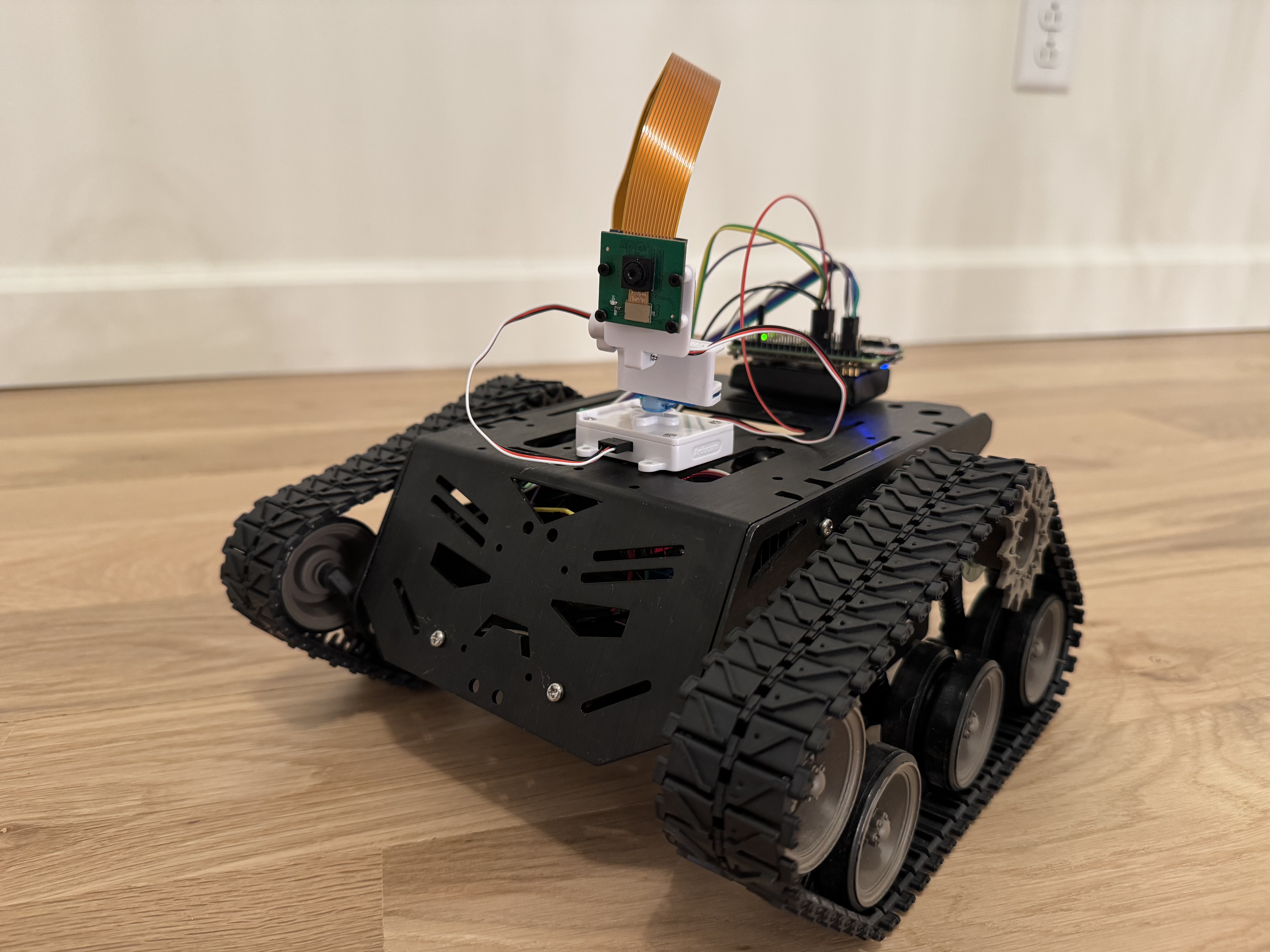
That’s how Sentinel was born. It’s a tracked robot running on a Raspberry Pi Zero 2 W, with a pan-tilt camera, controlled entirely through Home Assistant. Here’s how I built it, what went wrong, and how it all fits together.
The full source is on GitHub: github.com/arudyk/sentinel
The Hardware
I wanted to keep the build relatively cheap and use parts I could actually get quickly. Here’s what ended up in the final build:
| Part | Link |
|---|---|
| Raspberry Pi Zero 2 W | Amazon |
| Tracked robot chassis | Amazon |
| L298N motor driver | Amazon |
| PiSugar 3 battery | Amazon |
| ArduCam pan-tilt platform (PCA9685) | Amazon |
| ArduCam camera module | Amazon |
| ArduCam 30 cm ribbon cable | Amazon |
| Female-to-female breadboard jumpers | Amazon |
The tracked chassis was a natural choice — wheels would have needed a lot more mechanical work to avoid spinning in place. Tracks give you easy pivot turns just by driving one side forward and the other backward.
The Pi Zero 2 W is surprisingly capable for this use case. It runs a full Linux stack, handles MJPEG video encoding, serves a Flask web app, and controls GPIO — all on a 512 MB quad-core ARM. The trick is keeping everything lean.
The PiSugar 3 is what makes the whole thing self-contained. It’s a battery HAT that sits right under the Pi, handles charging over USB-C, and exposes battery percentage and voltage over I2C. It’s genuinely one of the nicest accessories in the Pi ecosystem.
Wiring It Up
The L298N connects to the Pi’s GPIO pins for both direction control and PWM speed control:
| L298N Pin | BCM GPIO | Function |
|---|---|---|
| IN1 | GPIO 23 | Right motor dir A |
| IN2 | GPIO 22 | Right motor dir B |
| ENA | GPIO 18 | Right motor PWM |
| IN3 | GPIO 17 | Left motor dir A |
| IN4 | GPIO 27 | Left motor dir B |
| ENB | GPIO 19 | Left motor PWM |
One thing that bit me early: you must connect Pi GND to L298N GND. The motors weren’t responding at all and I spent an embarrassing amount of time checking my Python code before I realized the GPIO signals had no common reference with the motor driver. Once I added that ground wire everything started working immediately.
The pan-tilt kit uses a PCA9685 PWM controller, which talks to the Pi over I2C:
| Wire | Pi Pin |
|---|---|
| VCC | Pin 4 (5V) |
| GND | Pin 6 |
| SDA | Pin 3 (GPIO 2) |
| SCL | Pin 5 (GPIO 3) |
The Software Stack
I went with Flask on the Pi — not FastAPI, not asyncio, just plain Flask. For a single-user robot controller it’s more than sufficient, and MJPEG streaming is trivially simple with Flask’s streaming responses. The whole server is maybe 150 lines.
Motor Controller
The motor controller wraps RPi.GPIO with a clean API and falls back to dry-run mode on a regular dev machine (it just logs to stdout instead of touching GPIO pins). This meant I could develop and test the entire web server without ever needing the Pi in the loop.
class MotorController:
    def forward(self, speed=None): ...
    def reverse(self, speed=None): ...
    def turn_left(self, speed=None): ...
    def turn_right(self, speed=None): ...
    def stop(self): ...
    def brake(self): ...
For a tracked chassis, turning is just driving the motors in opposite directions. No fancy steering geometry needed.
Camera Streaming
The MJPEG stream is the part I was most nervous about. Running video encoding on a Zero 2 W sounded like it might be a CPU nightmare, but picamera2 uses the VideoCore VI hardware encoder so the CPU barely notices it.
@app.get("/stream")
def stream():
    return Response(
        camera.generate(),
        mimetype="multipart/x-mixed-replace; boundary=frame",
    )
The generate() function is just a generator that yields JPEG frames with the right multipart headers. The browser’s <img> tag handles everything else — no WebSocket, no WebRTC, just a good old MJPEG stream.
Pan-Tilt (PCA9685 over I2C)
This is where things got interesting. The ArduCam pan-tilt kit uses a PCA9685 16-channel PWM controller. Rather than pulling in the full Adafruit CircuitPython stack (which is overkill for two servo channels), I drove it directly over I2C with smbus2.
The PCA9685 needs to be configured for 50 Hz PWM (standard servo frequency), then you write pulse width values to each channel:
def _init_pca9685(self) -> None:
    self._write_reg(_MODE1, 0x00)
    prescale = round(_OSC_CLOCK / (4096 * _FREQ_HZ)) - 1  # 121 for 50 Hz
    mode1 = self._bus.read_byte_data(self._addr, _MODE1)
    self._write_reg(_MODE1, (mode1 & 0x7F) | 0x10)  # sleep
    self._write_reg(_PRESCALE, prescale)
    self._write_reg(_MODE1, mode1)                   # wake
    time.sleep(0.005)
    self._write_reg(_MODE1, mode1 | 0xA1)            # auto-increment on

def _write_servo(self, channel: int, angle: int) -> None:
    off  = _angle_to_ticks(angle)
    base = _LED0_ON_L + 4 * channel
    self._bus.write_i2c_block_data(
        self._addr, base, [0x00, 0x00, off & 0xFF, (off >> 8) & 0x0F]
    )
Converting an angle (0–180°) to a pulse width tick count is straightforward:
_PULSE_MIN_US = 500
_PULSE_MAX_US = 2500
_PERIOD_US    = 20_000  # 50 Hz = 20 ms

def _angle_to_ticks(angle: int) -> int:
    pulse_us = _PULSE_MIN_US + (_PULSE_MAX_US - _PULSE_MIN_US) * angle / 180
    return round(pulse_us / _PERIOD_US * 4096)
One gotcha that took me a while to figure out: when I first tested the pan-tilt, pressing right moved the camera up, pressing up moved it left — the axes were completely rotated. Turns out the physical servo connections were swapped: channel 0 was actually the tilt servo and channel 1 was pan. And because of how the servo was mounted, increasing the tilt angle moved the camera up (opposite to the intuitive convention). The fix was swapping the channels and inverting the tilt:
def pan(self, angle: int) -> None:
    self._write_servo(1, angle)  # channel 1 = pan

def tilt(self, angle: int) -> None:
    self._write_servo(0, 180 - angle)  # channel 0 = tilt, inverted
Two lines of code after half an hour of head-scratching.
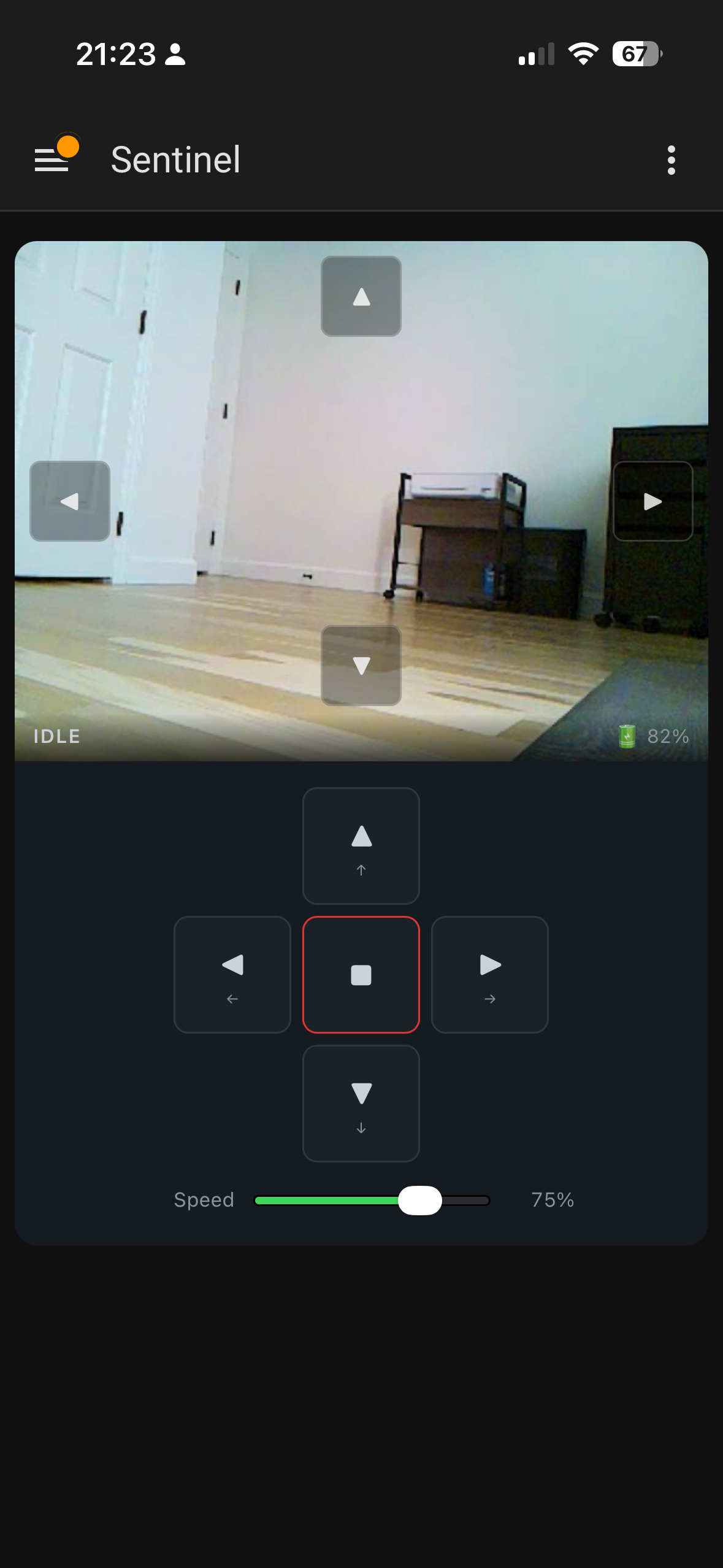
The Web UI
The web interface is plain HTML/CSS/JS — no build step, no framework, no npm. It loads instantly even on slow connections. The controls use pointerdown/pointerup events so it works on both desktop and mobile with the same code.
The camera stream is just an <img> tag pointing at /stream. When it errors out (robot goes out of WiFi range, Pi reboots) it automatically reconnects after 2 seconds:
streamImg.addEventListener("error", () => {
  setTimeout(() => {
    streamImg.src = `/stream?t=${Date.now()}`;
  }, 2000);
});
For pan-tilt I added transparent arrow buttons overlaid directly on the camera feed, plus IJKL keyboard controls. The hold-to-move behaviour is a setInterval that fires every 80ms while the button is held, incrementing the angle by 3° per tick:
const tick = () => {
  currentPan  = Math.max(0, Math.min(180, currentPan  + panDir  * 3));
  currentTilt = Math.max(0, Math.min(180, currentTilt + tiltDir * 3));
  sendPanTilt(currentPan, currentTilt);
};
btn.addEventListener("pointerdown", e => {
  tick();
  timer = setInterval(tick, 80);
});
btn.addEventListener("pointerup", () => clearInterval(timer));
Home Assistant Integration
This was the part I was most excited about. I wanted Sentinel to be a real HA device — not just a camera URL pasted into a generic card, but a proper integration with entities, a device page, and a custom Lovelace card.
The Integration
The integration is a standard HA custom component. It uses a DataUpdateCoordinator that polls /status every 5 seconds to keep all the entity states in sync:
class SentinelCoordinator(DataUpdateCoordinator):
    async def _async_update_data(self) -> dict:
        async with aiohttp.ClientSession() as session:
            async with session.get(
                f"{self.base_url}/status",
                timeout=aiohttp.ClientTimeout(total=5),
            ) as resp:
                resp.raise_for_status()
                return await resp.json()
Commands are sent as fire-and-forget POSTs, but wrapped in proper error handling so HA shows a notification if the robot is unreachable rather than silently failing:
async def send_command(self, action: str, speed: int | None = None) -> None:
    try:
        async with aiohttp.ClientSession() as session:
            async with session.post(
                f"{self.base_url}/command",
                json={"action": action, "speed": speed},
                timeout=aiohttp.ClientTimeout(total=5),
            ) as resp:
                resp.raise_for_status()
    except Exception as err:
        raise HomeAssistantError(f"Sentinel is unavailable: {err}") from err
The integration exposes the robot as a single HA device with a full set of entities: drive buttons, speed number, pan/tilt numbers, battery sensors, camera health binary sensor, and the live camera stream.
The Camera Stream in HA
Getting the camera stream to work remotely (through HA, not direct Pi access) was trickier than expected. HA proxies camera streams through /api/camera_proxy_stream/{entity_id}, but this endpoint requires an access_token that’s stored in the camera entity’s state attributes. The token isn’t in the URL by default.
The fix was reading the token from the HA state object in the Lovelace card:
_streamUrl() {
  const entityId = this._e('camera', 'camera');
  const state = this._hass.states[entityId];
  const token = state?.attributes?.access_token;
  const base = `/api/camera_proxy_stream/${entityId}`;
  return token ? `${base}?token=${token}` : base;
}
Without this, the stream worked fine on the local network but showed a black box when accessed remotely through HA.
The Lovelace Card
The custom Lovelace card is a Web Component that renders the camera stream, pan-tilt overlay arrows, drive D-pad, and speed slider all in one:
type: custom:sentinel-card
entity_prefix: sentinel
The card uses HA’s callService API to trigger drive buttons and set number entities for speed and pan/tilt. One thing worth noting: HA’s camera entities rotate their access_token on restart, so the card watches for token changes in _update() and refreshes the stream URL automatically.
Deployment
Since the Pi doesn’t have a monitor and I don’t want to SSH in every time I push a change, I wrote a small deploy script that pushes to GitHub and then pulls on the robot:
#!/usr/bin/env bash
REMOTE="${SENTINEL_USER:-sentinel}@${SENTINEL_HOST:-192.168.1.138}"

git push
ssh "${REMOTE}" "cd ~/sentinel && git fetch origin && git checkout -B main origin/main && sudo systemctl restart sentinel"
ssh "${REMOTE}" "sudo systemctl status sentinel --no-pager -l"
For the HA integration, it’s deployed from a separate home server repo that clones the latest sentinel at deploy time and rsyncs the HA files into place.
What I’d Do Differently
Better cable management. Individual jumper wires get messy fast. A cleaner solution would be a connected ribbon cable that bundles everything together rather than a rats’ nest of loose wires.
Mount the Pi outside the chassis. I originally had the Pi Zero tucked inside the metal chassis — and the WiFi signal was terrible. Latency spiked, the stream stuttered, commands were sluggish. Mounting the Pi on top of the chassis fixed it immediately. A metal enclosure is basically a Faraday cage, and the Zero’s tiny onboard antenna doesn’t stand a chance inside one.
Authentication on the web API. The /command endpoint has no auth, but since access is gated through Home Assistant (which handles its own auth), I’m not worried about it. Direct Pi access is LAN-only anyway.
What’s Next
The one thing that still bugs me about the current setup is having to manually plug in the USB-C cable to charge. The robot is useful precisely when I’m not home, so if the battery dies while I’m away there’s nothing I can do about it.
I want to build a charging dock using magnetic pogo pin connectors. The idea is to mount the female pogo pins on the dock at a fixed position, and the matching male pins on the underside or back of the robot. When the robot drives onto the dock, the magnets pull the connectors together and charging starts automatically — no plugging in, no alignment fussing.
The PiSugar 3 already handles the charging circuit, so the dock really just needs to deliver 5V to the right pins. The tricky part will be making the robot reliably find and align with the dock, which is probably a computer vision problem for a future weekend.
Wrapping Up
The whole project took a few weekends spread over a month. Most of that time was hardware — wiring, cable management, figuring out the servo directions. The software side came together quickly once I had a working robot to test against.
The thing I’m happiest about is how well it integrates with Home Assistant. Being able to drive it and watch the feed from the HA app anywhere in the world, with battery status and everything right there, is genuinely useful and not just a toy.
If you build one, or do something different with the same parts, I’d love to hear about it.
Source: github.com/arudyk/sentinel
raspberry-pi home-assistant robotics hardware
2069 Words
2026-03-18 20:00 -0400 (Last updated: 2026-03-18 20:00 -0400)